![\includegraphics[width=9cm]{pixstore.eps}](img1.png)
|
This Hardware/Operating System/DataBase Management System Design Document (HDD) for the Visible and Infra-red Survey Telescope for Astronomy (VISTA) Science Archive (VSA) and Wide Field Camera (WFCAM) Science Archive (WSA) gives an overview of the hardware used and needed for data storage as well as for the data servers used for the VISTA Data-Flow System (VDFS) at the archive centre (Wide Field Astronomy Unit (WFAU) at the Institute for Astronomy (IfA), University of Edinburgh (UoE)). The reason for considering hardware, Operating System (OS) and DataBase Management System (DBMS) together is that the three are intimately tied together; for example, optimal DBMS operation is not always possible for a given hardware and OS configuration. Networking is also considered as copying the data from the data processing centre (Cambridge Astronomical Survey Unit (CASU) at the Institute of Astronomy (IoA), University of Cambridge (UoC)) to WFAU plays a significant role.
This HDD is intended to be a reference for software engineers and scientists working on the VDFS project. A primary goal of the document is to specify the V1.0 VSA hardware in enough detail to enable orders to be placed with vendors to acquire the necessary equipment. This document will also discuss how we plan to move from phase four (see Management and Planning Document (MPD) [AD06]) through to the phase five system.
In our development of the WSA we have had to deal with some tensions that have informed our work on the VSA. The need for timely development work (e.g. hands-on experience) has to be balanced against the general best practice of delaying hardware purchases as long as possible (for reason of Moore's Law). Further, the timescale for significant developments in computer hardware technology and experience with the WSA imply that over the lifetime of the VSA the archive hardware solution is likely to change and a migration from one system to another will almost certainly be needed (this is even more so for the overall VDFS). Hardware configuration has many complicated variables and it is only via experimentation that a lot of questions can be answered.
Fortunately hardware manufacturers (e.g. Sun MicroSystems, IBM, CompuSys) are open to donation of discounts, money and/or hardware for what they see as big projects in Research and Development (R&D). In addition many hardware suppliers are open to loan of high specification equipment meaning that experimentation is possible with no outlay on hardware. The commercial hardware and DataBase (DB) software businesses (i.e. Microsoft/SQLServer, IBM/DB2, Oracle/Oracle) are open to supplying expertise and advice to large DB developers and, more importantly, to supplying licenses that are heavily discounted or even free of charge. Finally; many of the hardware issues facing the VDFS overlap with similar ones in other IT projects in the UK (e.g. initiatives at the National e-Science Centre (NeSC), within AstroGrid) and farther afield in Europe (e.g. the Astronomical Wide-field Imaging System for Europe (ASTRO-WISE) [1], the European Southern Observatory (ESO) Next Generation Archive Systems Technologies (NGAST) [2]).
In this document the hardware components that are being used to build-up the VDFS are described. The design of this system is intended to ably meet the highest requirements that VISTA and WFCAM may need so that should VISTA produce less data that it might then there would be potential for savings in future. In Section 4 we describe the required storage hardware for the pixel data archive and the catalogue data archive and the required arrangement of the servers. The CASU to WFAU network connection is discussed next in Section 5, the backup system is then considered in Section 6. Finally, in Section 7, the local infrastructure (Local Area Network (LAN), equipment accomodation etc.) and the VDFS requirements of it are detailed.
The Appendices can be found in Section 8 and applicable documents are listed in Section 10.
The clear requirement to arise out of the Science Requirements Analysis Document (SRAD) [AD01] is for a phased approach so that a VSA with `standard' functionality is available at first light, enabling immediate science exploitation. Subsequent to the initial VSA phase a fully functional archive system is to be made available one year after survey operations begin in earnest. There is also a clear split in the requirements for volume and access speed between the catalogue and processed pixel data (from here on in `pixel data' will mean processed pixels as generated by the CASU processing pipeline and toolkits; note that there is no requirement for the VDFS to store the raw pixel data). The VDFS use cases require user interaction with catalogue data (i.e. complex queries returning results in as close to real time as is feasible) for data mining and data exploration while high volume pixel data use cases are less time critical (i.e. users would be prepared to wait for the results of operations on large pixel volumes since these would be executed relatively rarely).
The fundamental requirement on the VISTA system hardware concerns the volume of data that will flow into the archive and that rate at which that data flow occurs. In Appendix 8.1 we give an analysis of the data volumes and rates based on current knowledge and reasonable assumptions.
The outline hardware requirements are therefore as follows:
The phased approach and volume/speed split is reinforced in the light of the hardware considerations stated in the previous Section: we will implement two distinct hardware solutions to satisfy the user requirements. If one subsequently becomes a viable solution for all the users' requirements but at the same time at a reduced cost then migration from one solution to the other will be straight forward. The phased approach also maximises the possibility of exploiting the most recent advances in computer technology since we will not be wedded to one hardware solution from the start and will delay as long as possible each hardware upgrade acquisition (though changes in OS/DBMS will need to be done within the development period for the VSA due to the software changes this would imply).
The baseline requirements for the pixel storage are high capacity and expandability to the tune of 88 TB/y. Low cost, mass storage of pixel data is a solved problem: ESO's NGAST [2] employs low cost IDE disks connected to mid-range CPUs to provide multi-TB capacity. We have implemented a similar solution to NGAST for VDFS pixel storage to date with the addition of using a Redundant Array of Inexpensive Disks (RAID; Section 8.3) (level 50) which gives us fault tolerance against individual disk failure and lowers disk management overheads - NGAST apparently does not currently use RAID. The OS is Debian Linux, we are using the locally supported Linux distribution to save on server management overheads and Debian is well known, in fact primarily so, for reliability.
The pixel data, stored in FITS [15] files, are stored as flat files in an observation-date driven directory structure. The FITS data stored consists of images (and also catalogue FITS binary tables) produced by the CASU processing pipeline and tool kits - for more details see the Interface Control Document (ICD) [AD02]. The pixel server hardware consists of TB-scale file servers employing 3Ware Escalade IDE RAID controllers and between 16 and 24 disks of between 250 GB and 500 GB each in capacity in two rackmount units yielding between 3 TB and 10 TB each of storage space after RAID overheads (see Figure 1). This system is modular and has been expanded over the last few years such that the total capacity is now approximately 32 TB
New changes in technology have, however, introduced a newer type of server called Network Attached Storage (NAS). Essentially this uses the same technology as we have been using up to the present with the exception that it is designed with our express purpose in mind. NAS is simply a stack of disks that use RAID internally and provides a single external interface over a network connection. We expect to use NAS in future to provide our pixel data storage needs as it is marginally cheaper, easier to manage and has less infrastructure overheads than our current system of modules.
The VSA V1.0 and V2.0 hardware solutions will be the same in intent as the current WSA solution using NAS instead of homegrown storage modules. We will add more NAS nodes as and when needed, phasing purchasing to maximise the return per TB cost and to take advantage of any new developments in storage technology (e.g. we anticipate the cost competative availability of 600 GB IDE hard disk drives by early 2007 - though 750 GB IDE hard disk drives will likely also be available, this would be at a premium in cost).
The baseline requirements for the catalogue hardware are:
Single disk performance for 100 percent sequential reads is typically in the range 10 MB/s to 60 MB/s, depending on make, model and controller (we note in passing that the commonly held belief that SCSI interfaced disks are always faster than IDE is not based on experimental facts for 100 percent sequential reads [3] - it is only during random reads that the two times faster seek time of SCSI disks produces higher Input/Output (IO) bandwidth). For a typical single disk bandwidth of 60 MB/s (see Section 8.4), trawling a 300 GB table for a query on non-indexed attributes (e.g. a data mining query searching for a rare type of astronomical object, the search being predicated on an unusual combination of rarely used attributes) would take about ppp hours (ignoring data processing overheads). Obviously the only way around this fundamental limit is parallelisation. This could be achieved using a PC farm - small numbers of disks attached to many individual CPUs - or by using a RAID array - attached to a single CPU where striping (Section 8.3) across many disks allows parallelisation during IO. Both of these solutions increase bandwidth by aggregating the bandwidth of many disks to achieve better transfer rates.
Three designs of catalogue storage were considered, the PC farm method (quickly discounted due to expense in terms of money, power and heat as well as much greater management costs) and two variations of a RAID system, one using IDE disks and one using SCSI disks. Initially the performance of IDE disks was greater than that for SCSI disks however the trial of Ultra320 controller cards (with twice the bandwidth of the original, older Ultra160 controller cards) means that SCSI became the clear leader in performance. This was confirmed as true once actually put into service since, although a lot of the testing was done using 100 percent sequential reads, the choice of DBMS and requirement to process user requests interactively (rather than queueing them into a batch job system) meant that the two times greater data seek speed of the SCSI disks helped significantly speed up the system at times when it was most needed.
This has lead us to build a SCSI based RAID system using RAID level 50 (Section 8.3), as was done in the case of the pixel servers. This has had the added bonus of allowing us to reduce the number of servers that might otherwise have been needed to maintain the size of storage capacity we will need to have (as 15 SCSI devices may be added to a single SCSI channel though at the cost of sharing the bandwidth between the devices). Our current base server is a dual CPU, dual core machine with up to four SCSI controller cards each with four channels each connected to an individual level 5 RAID array, each card then stripes the data it receives across pairs of arrays it controls. For example; a machine with thirty two 300 GB disks split across four RAID level 50 arrays would have a total of 16 TB of space across four drives.
The baseline requirements for the catalogue OS/DBMS choice are flexibility (e.g. provision of an industry standard Structured Query Language (SQL) interface, ability to cope well with TB of data) and ease of use. Previously we have implemented WFAU data services with ad hoc flat file systems but such solutions are not flexible or scalable to large data volumes. With the development of the VDFS we have followed the SDSS science archive developments in order to benefit from their experience and software development. Our experience with Microsoft (MS) SQLServer as used with the Six-degree Field Galaxy Survey (6dFGS) [6], SSS [7] and WSA [19] confirms that MS Windows/SQLServer is an able choice for the VSA and the recent release of an update to this software means that this is liable to continue to be true as the VDFS Science Archives grow in size.
MS SQL Server has a useful feature in that it is able to spread a DB across many disks (no doubt introduced due to drive size limitations) and so, although the drives on our base machine are only 2 TB in size, we are able to store an 8 TB database with no loss of internal IO bandwidth. By doing this we are also, effectively, striping the data across the four drives giving yet another boost to the bandwidth and thus speed with which data may be accessed.
Given our own experience with curating and serving the TB scale SSS and WSA, and on the advice of our colleagues in the SDSS science archive group, we have implemented a hardware design that consists of three independent SQL servers: a so-called `load' server and two publicly accessible servers. The main reasons for this are:
To provide an interface to our servers as well as to maintain tighter security controls we have used our experience in setting up secure data services to build a web server front end for access to the VSA. This same interface system has already been used for the WSA which has improved it to an even greater degree. To this end we have one server for the purpose of securely providing the VDFS interfaces to the outside world. Our existing DB servers are isolated from the Internet (it is highly inadvisable to expose MS Windows database servers directly to the Internet) as are our pixel storage servers (reducing our exposure to security glitches). Access to the servers, and our other online services, is provided on a Debian Linux web server using Apache and its Tomcat extension (which proxies SQL querys to the DB servers in question). The requirements for this web server are not high, approximately a 200 GB hard disk, a mid-range CPU with, a slightly exceptional, 2 GB of memory - used for user access-time pixel manipulation.
We did not anticipate any problems in achieving the required network bandwidth to routinely transfer processed data from CASU to WFAU for WFCAM; however transfering both VISTA and WFCAM data from CASU to WFAU will require more than can currently be obtained using our standard network link.
The requirement for external network connectivity is 17 MB/s continuous bandwidth. All UK HEIs and data centres, including WFAU and CASU, are interconnected using the Joint Academic Network (JANET; [8]). We have tested the current, standard bandwidth between CASU and WFAU (see Appendix 8.6) and measured a bandwidth of up to 18 MB/s (over very short periods while the end servers were not loaded); we note that further tests [9] between CASU and the LEDAS data centre at Leicester University have achieved about 4 MB/s while typical rates between any two JANET sites are less than 1 MB/s.
We have also consulted our local networking experts within Astronomy Technology Centre (ATC)/IfA Computing Support and Edinburgh University Computing Services (EUCS), investigated transfer protocols and mapped out the network between WFAU and CASU (see Appendix 8.5). Noteworthy points are as follows:
The fundamental requirement for data security is that backups are essential for all data. Raw data are not a WFAU concern but we note in passing that offline raw data copies of WFCAM data are held at JAC and CASU (ESO will also have a raw data copy). Processed pixel data and standard catalogue detection products associated with those images will be stored on spinning disk and in an offline archive at CASU; processed pixel and catalogue data will, of course, be held online on spinning disk at WFAU on fault-tolerant RAID level 50 systems (see Section 4). We do not expect to make offline copies of the large volume processed pixel data because in the event of data loss the affected files will be recoverable from the CASU backup. However our experience is that catalogue product backups are highly advisable when wishing to provide a reliable service to users; for example, our SSS data needed to be recovered from removable backup media once in the past, avoiding an online service interuption of several months. Hence we use a high capacity system for removable media backups: `Ultrium' LTO-2 tape. There are several features of these systems that make them ideal for VSA catalogue backups:
We note that per TB tape is still the cheapest, most flexible and most secure method of making removable media data copies.
We will isolate the VSA hardware from the site-wide LAN, as we have with the WSA, so as not to impact general on-site network performance with the heavy VISTA data transfer load expected. To this end a small, 125 MB/s LAN specifically for the VSA and WSA will be used. The mass storage pixel server and web server are internally firewalled and connect to the SRIF connection and to this Science Archive LAN. The resulting overall picture of the VSA hardware is shown in Figure 2 (the WSA hardware currently being similar but with more mass storage servers).
![\includegraphics[width=14cm]{wsalan.eps}](img2.png)
|
Our present data service hardware is accommodated in a secure, air conditioned area protected by automatic fire extinguishing equipment. Sufficent power and space for the VSA V1.0 hardware are available in this same room; with some rearrangement we anticipate that additional V2.0 equipment may also be able to be accommodated in this room for the next year. After this we expect being able to refurbish an existing computer area (which has the necessary automatic fire extinguishing, power and network infrastructure already in place) for the purposes of VSA hardware.
Effort for system set-up and management is available within the existing staff effort allocated to the VSA project (see MPD [AD06]). A small amount of additional computing support is available as part of the general allocation available to WFAU from the ATC/IfA Computing Support team. This includes staff experienced in networking and management of both Linux and MS Windows systems.
The VISTA User Requirements details this aspect of the system and states that the VDFS (with respect to VISTA data) shall be able to process and archive data at a peak rate of 1000 GB per day for ten days and a sustained rate of 650 GB per day (equivalent to 237 TB per year) long-term, including typical downtime percentages. These volumes are uncompressed pixel data including calibration frames. These rates are necessary to enable keeping up with input data and simultaneously reprocessing `old' data with improved algorithms. More quantitively; the intention is for VDFS to process sixteen high-volume nights within ten calender days and two and a half mean years of data within one calender year (where the volumes are estimated below).
Each exposure is 268.8 MB of raw data (before Rice compression). The maximum data rate for which the data handling system is designed is one exposure per 10 s for fourteen hours; i.e. 1350 GB per night of observing. One exposure per 20 s for thirteen hours; i.e. 630 GB per night of observing is a more reasonable high-volume night given overheads. A median night (i.e. typical observing cadence) is estimated to be one exposure per 60 s for thirteen hours; i.e. 210 GB. Assuming ten nights engineering time per year and fifteen percent loss of the remaining 355 days to weather gives data for about 300 nights a year. Assuming also this is divided as 255 median nights of 210 GB and 75 high-volume nights of 630 GB this gives 95 TB per year at a mean rate of 315 GB per observing night; or 260 GB per calender day (on dividing 95 TB by 365 for a daily equivalent mean rate), all uncompressed.
Note that the distinction between median and mean is relevant here. The mean is one and a half times higher since some nights, e.g. shallow surveys, will have about three times the median data rate but most nights will not be much less than the median.
Assuming that the compression rate is comparible to that of the WFCAM data (from about 64 MB to an average of 17 MB) then the processed volume of pixel science frame data for VISTA would be about 84 GB per observing night; or 69 GB per celender day. However, the total amount of data needing ingestion, curation and release is greater due to interleaving, stacking and cataloguing so, again assuming that the ratio is comparable to WFCAM data (from an average of 17 MB to an average of 42 MB) the processed data rate for VISTA is estimated to be 207 GB per observing night; or 171 GB per calender day. The total per year would be about 61 TB (62319 GB), approximately four times the data rate for WFCAM (see Appendix 8.2).
The above assumptions are possibly incorrect though due to different microstepping and interleaving usage with VISTA, this would potentially as much as double the amount of data needing transfered. We have taken this into account when designing the hardware system and all parts of it would be able to process this larger amount of data.
The data rates for WFCAM have historically been (and thus are likely to continue in the same vein) as detailed below. It is worth bearing in mind that these rates are for processed pixel data after Rice compression and catalogue data as produced by CASU and therefore are not directly comparable with the rates for VISTA.
A single processed science frame is about 17 MB (after Rice compression) with the data for each processed science frame totaling about 42 MB (after Rice compression). The average number of science frames per night (an average of the period between 25th August 2005 and 6th February 2006 - this period contained 140 nights when data was observed and processed) is about 1850; i.e. 76 GB per mean night of observing. The average number of science frames in a high-volume night of observing (from the period between 25th August 2005 and 6th February 2006) was 3200; i.e. 131 GB for that high-volume night of observing. In the period of semester 05B (i.e. over 166 nights) processed data has been produced for 140 nights; i.e. 85 percent of nights had processed observations taken). The total amount of data processed, ingested, curated and released for this period amounts to 10640 GB (10.4 TB), all compressed; or 76 GB per observing night; or 64 GB per calender day.
These figures include calibration frames, describe Rice compressed data and relate only data from the period between 25th August 2005 and 6th February 2006 (semester 05B), however the averages for semesters 05A and the start of 06A (28th April 2006 to 31st May 2006 inclusive) are, respectively, 80 GB per observing night; 71 GB per calender day and 54 GB per observing night; 47 GB per calender day.
On the basis that WFCAM is only attached to the telescope for two-thirds of the year the actual data transfer rate necessary between CASU and WFAU in the case of WFCAM (though not in the case of VISTA) is even lower than the per calender day rate, the rate is actually (based on the semester 05B rates) about 43 GB per calender day. A total of 16 TB (16434 GB) has been processed for one version of the two 05 semesters (an average of 45 GB per calender day of 2005) - a total of 25 TB (25280 GB) has been processed for the two 05 semesters due to the processing of semester 05A three times (an average of 69 GB per calender day of 2005).
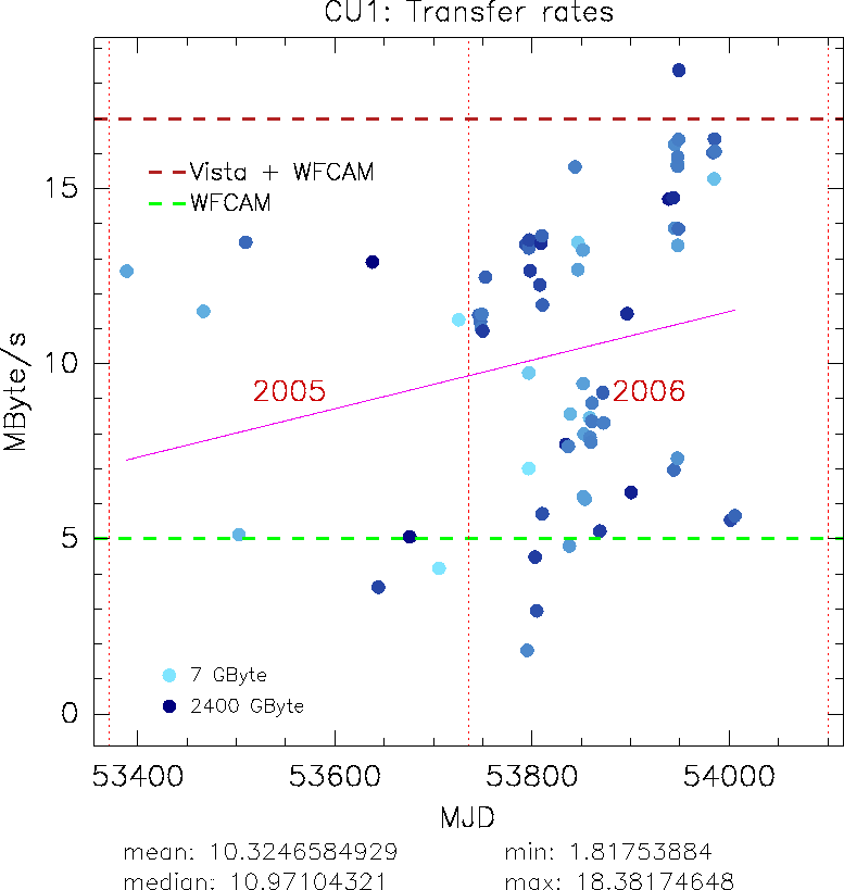
The mean transfer rate of data from CASU to WFAU for the period between the beginning of 2005 and February 2006 (when the UKIDSS Early Data Release happened) was 9.46 MB/s. Most transfers were performed at night and/or at the weekend to boost the transfer rate with little or no contention for network bandwidth on the transfering machines at CASU and WFAU.
RAID is a technology which allows inexpensive disks to be used for critical applications where fault tolerace is necessary by using redundant hardware to overcome the falibility of cheap disk drives. Essentially RAID is a system that the OS uses to access the disk drives and as such it can come as two flavours, either a software RAID system (i.e. a program run by the OS) or as a hardware RAID system (i.e. an interface and controller card that provides a simple interface through which the OS accesses the data on the disk drives, simplifying the process for the OS). Needless to say, despite implications and advertisments to the contrary by software companies, the hardware solution is faster, more reliable and a much more efficient solution (though potentially slightly more costly when RAID was first developed). RAID systems can also be of different types, these different types provide differing amounts of fault tolerance but can also be combined to provide even greater levels of protection. These types are:
With the VDFS system we have chosen a hybrid system (as it is normal to do with large RAID systems), we are using what is known as a level 50 RAID system, essentially we have multiple arrays on a single RAID controller card that are checksummed arrays, these `sub-arrays' are then striped to increase performance and to reduce the number of drives the OS has to handle so, for example, a machine with twelve 500 GB disks and one RAID controller card would have two six-disk checksummed arrays (each normally with a capcity of 3 TB but in a checksummed array they only have a capacity of 2.5 TB), these two checksummed arrays are then striped to give a single 5 TB drive which the OS can then treat as a single drive but that can have two disks fail (one from each checksummed array) before any data are lost.
In the preliminary design phase of the WSA we suggested that the PC farm route may be a good option since as well as achieving high aggregate IO, the system automatically has at its disposal large processing power that may come in useful for advanced applications. However, the disadvantage of the PC farm is in expense and management and it turns out that a trawl rate of less than 1000 s can be achieved, at least for moderately sized tables, using inexpensive RAID technology, e.g. [4]. In this study, by careful design with due regard to disk, disk controller and PCI bus bandwidth limits, aggregate IO rates of well over 300 MB/s were achieved. This study used Ultra320 SCSI controllers along with SCSI disks and matched the number of disks and their bandwidths to the measured saturation limits of the controllers; note that software striping across the disks was employed. A useful figure to come out of this and other similar studies is that the manufacturer's `burst' transfer specification for any device (e.g. 320 MB/s for Ultra320 SCSI controllers) will typically fall by 25 percent for sustained IO rates. So, for example, Ultra160 controllers are capable of sustaining IO rates of 120 MB/s - hence a maximum of 3 disks, each giving 40 MB/s, were attached to each controller in [4]. The key point to note concerning optimising aggregate IO rates for a hardware system is that the saturation limits of each component in the IO chain - PCI bus, interface connection card, disk controller(s) and disk(s) - must be carefully considered and matched such that no one component limits the potential performance of the rest (the ultimate limit of a single CPU system is the CPU and PCI bus, which can typically shift data at rates of 0.5 to 1.0 GB/s).
The disadvantages of the configuration in [4] as regards the WSA requirements are, for optimum performance:
Our catalogue server design for the VSA will mirror that of the WSA (in fact the same servers will be used for both as it is capable of maintaining catalogues for both Science Archives initially). This system employs the IO advantages of [4] using SCSI disks and RAID controllers to achieve the necessary storage capacity, fault tolerance and high aggregate IO, all at reasonable cost. The system is a dual processor system employing two Opteron dual core processors which has followed on from the dual processor Xeon system used in the testing performed before purchasing the initial WSA hardware (see Appendix 8.4) using real-world astronomical queries and the OS/DBMS choice already made for the WSA (see below; again, more details are given in Appendix 8.4). The results shown in Figure 3 are from tests performed before purchasing the initial WSA hardware where several trawl-type queries were executed per disk array configuration (all RAID level 5) using a 5 GB table to ensure no misleading results from caching anywhere in the system (5 GB being larger than the systems memory capacity).
![\includegraphics[width=14cm]{idebms.eps}](img3.png)
|
The performance of the fibre-to-IDE controllers used here is not as good as might be expected given that the single IDE disks are capable of reading at sustained rates of 40 MB/s; additionally the saturation performance of one controller (80 MB/s) is not on its own up to the requirements. We suspect (but do not yet have experimental evidence to support this suspicion) that the drop in per-disk performance to 10 MB/s and the saturation at 80 MB/s are inherent to the RAID controllers, hence it is the price to be paid for high capacity and fault-tolerant inexpensive disk arrays. We have used hardware RAID level 0 (striping) over the logical volumes presented by two RAID controllers to further parallelise the IO up to 150 MB/s.
Given the large range of possible hardware solutions and configurations that would be implemented for the VDFS, we have been conducting a test programme using our existing, and also loaned, hardware to determine the best compromise between performance, cost, scalability and complexity. The tests have taken the form of employing twenty real-world astronomical queries [18] developed for the SQL Server implementation of the SSS or SSA. These queries include several examples pertinent to expected usages of the VDFS, e.g. joint queries with the SDSS; however for the purposes of trawl benchmarking we have used a subset of six of the twenty queries that trawl the multi-epoch, multi-colour merged SSA catalogue corresponding to the SDSS-EDR regions. This catalogue is 4.87 GB in size. The performance figures are summarised in Table 1.
|
The important point to note here is that the use of SCSI Ultra320 RAID cards makes a large difference to throughput, this is both clear from Figure 3 and the values in Table 1. The difference between use of hardware RAID and software RAID become a much greater issue if the server in question is loaded (i.e. is using it's processors for other large jobs) when it then needs to do data retrievals... in this scenario it turns out that the speed of the CPU limits the data transfer rate rather than any of the hardware.
Network morphology is illustrated in Figure 4. The circle in the top left shows the location of the current WFAU data servers on the network: thoth (SSS and WSA web server) and djedefre (transfer server for the pixel data from CASU) are on both the SRIF network (running at 125 MB/s - equivalent to 1 Gbit/s) as well as the VDFS private area network (also running at 125 MB/s). Amenhotep (WSA and SSS DB server) and thutmose (Sloan DR2 and DR3, TWOMASS et al. mirror) are on the VDFS private area network.
![\includegraphics[width=14cm]{network2.eps}](img4.png)
|
Network in and around the University is illustrated in the top right of Figure 4. The Strategic Research Infrastructure Fund upgrade to the Edinburgh network infrastructure is depicted in the softbox labelled SRIF. The core of the SRIF network can be thought of for present purposes as a set of four 125 MB/s fibres running between a pair of routers. One of these is connected to the University network and the other is connected to a router (at the university King's Buildings) to which the ROE LAN attaches. That router is then connected to a router to which EaStMAN attaches and that router, in turn, connects to the Edinburgh BAR (Backbone Access Router), which connects to the JANET backbone. All the connections shown here are 125 MB/s. A 125 MB/s link from the SRIF router to the ROE SRIF link attaches straight to the BAR, so that SRIF traffic can be sent to JANET on a separate route from UoE and EaStMAN traffic.
The rest of Figure 4 shows the basic morphology of JANET. Traffic from the Edinburgh BAR gets to Cambridge via the SuperJANET Core Routers (SCR) in Edinburgh, Leeds and London and there is a 312 MB/s link from the London SCR to the Cambridge BAR, which attaches to EastNet and the Cambridge University network. The links between SCRs run at 1250 MB/s, these links are currently have the same bandwidth as the UKLight links though SuperJANET5 will upgrade the JANET links when it is rolled out.
Most data transfer over the Internet proceeds through the use of TCP/IP, which is a suite of protocols.
IP (Internet Protocol) is a protocol for sending packets of data. It includes no notification of arrival, nor does it guarantee the order in which packets will arrive or when they will arrive.
TCP (Transmission Control Protocol) sits on top of IP, usually implemented in the kernel of Unix machines. Its operation can be best understood through a fiction in which there is a duplexed data stream (send & receive) running between applications sitting on the machines at each end of a data transfer: it is conventional to refer to one of these connections as `a TCP'. In this fiction, data either arrives in the correct order or the connection is broken. The sender numbers packets and requires acknowledgement of receipt of the packets. The sender buffers data packets until it receives an acknowledgement that the particular packet has been received, or until a time-out occurs due to a broken connection. So, clearly, if the sender's buffer is too small, it may fill up before the first acknowledgement is received, at which point it has to stop sending more packets. The acknowledgement is in the form of an indication of how much space is available in the buffer at the receiving end and the sender acts conservatively on that information, so that, if the buffer space at the receiving end is decreasing, it slows down the speed at which it despatches more packets. So, a larger buffer at the receiving end is desirable, too (the obvious inference would be to try to have as large a buffer at either end as possible and there would seem to be no reason to limit the buffer sizes, were it not for the fact that doing so would tie up possibly unnecessarily large amounts on memory in the two end-station machines). The receive buffer will be filled before the first acknowledgement is received by the sender if its size is less than the product of the data flow rate into the connection (assumed constant) and the round-trip delay time along the connection. This is called the Bandwidth-Delay Product (BDP) and it is a very useful quantity in analysing network performance.
The fundamental limit in the delay is the light-travel time between the end-stations but in realistic systems the overall delay is significantly above this limiting value due to processing delays, etc. As the distance between the end-stations increases, the delay time increases, more data is in flight and the receive buffer must be larger to cope with it. For example, given the delay time measured in tests between Edinburgh and Glasgow, 2.5 MB buffers would be required for a 125 MB/s link. Tests with a large-buffered system have attained transfer rates something like 55 MB/s for this dedicated connection, which is close to the speeds of the internal buses in the machines, showing that, with correct configuration, the limiting factor can be the hardware at each end.
The default TCP buffer size is 64 KB and the round trip light travel time between Edinburgh and Cambridge (1000 km round trip) is about 3 ms. This would suggest that the default buffer size could support a transfer rate of about 6.4 MB/s, which, while sufficient for WFCAM, is not sufficient for VISTA. However, tests record round trip travel times of 15 ms, so the default buffer size cannot handle the sustained 17 MB/s needed for the VDFS.
SCP is an application that runs a single TCP connection and has very low processor overheads if properly configured. The standard version of SCP, however, has an issue in that it assumes that the TCP buffer will never be more than 64 KB and therefore has a hard limit of a 64 KB buffer itself. This has been rectified by a newer version called HPN-SCP which has no limit on the buffer size and allows it to be set on a per connection basis. This combined with the VDFS software being able to run multiple SCP connection in parallel means that higher aggregate bandwidths may be attained even in the face of higher traffic loads or greater contention for the bandwidth that exists on the networks we cross.
Figure 5 shows the specified network bandwith between ROE and CASU at each hop in the chain represented in Figure 4 when connecting to the JANET backbone via the SRIF network.
![\includegraphics[width=12cm]{stdnetpic.eps}](img5.png)
|
|
|
To test the round trip time and measure real transfer rates to compare with those specified in Figure 5, transfer of data was tracked with traceroute and logs of the transfers that took place for WFCAM data were mined. traceroute measures network round-trip time by sending varing-sized UDP (User Datagram Protocol) packets into the network and waiting for ICMP (Internet Control Message Protocol) messages in response. Table 2 summarises the results and Figure 6 show the historical data as obtain from WFCAM transfers. It should be noted that the measured routd trip time figures can be quite inaccurate as only small packets of data are being sent during tests; The main point worthy of note here is there is a large available bandwidth between the Cambridge and Edinburgh BARs and that a sustained transfer rate of 18 MB/s can be achieved when the end servers are not loaded, however this rate is not to be depended upon as the average rate over very long periods of time, as shown in Figure 6, is a better indicator of the longer term bandwidth that we are able to make use of.
When the current iteration of JANET [8] (SuperJANET 4) was originally commissioned it was expected that the backbone (the sort of tracffic that JANET carries) network traffic would increase at the same speed as it had during the life of the previous iteration of JANET (SuperJANET 3), which was also the speed at which local site traffic had been increasing in the institutions that JANET served. Due to much improved caching systems, the rising cost of transatlantic traffic and greatly improved client software optimisation and compression the growth of backbone traffic merely grew by 150 percent (rather than quadrupling). This meant that about half of the infrastructure (after allowing for an extension of SuperJANET 4's lifetime) that had been set aside for future use by JANET was not needed. This infrastructure lying dormant attracted the attention of research groups needing a large amount of bandwidth or dedicated network links (primarily those associated with the new CERN (Conseil Europ�en pour la Recherche Nucl�aire) Large Hadron Collider (LHC)). These interested parties banded together with a proposal for JISC (Joint Information Systems Committee), who oversee JANET, and succeded in convincing JISC to setup and fund the development of a UK equivalent of the StarLight (USA) and NetherLight (Netherlands) networks. These networks are darknets, groups of mutually exclusive point-to-point connections that do not allow anything but project specific traffic on their dedicated link to the site at the other end of the link.
Some examples of projects already using UKLight (and it's connections to StarLight and NetherLight) are:
We have submitted a proposal to UKLight, which has now been accepted, for a dedicated point-to-point 125 MB/s link from CASU to WFAU. This link, being a darknet link, would be for the sole use of the VDFS and thus would only transfer VDFS data. Having this link will avoid slowdowns in our transfer rates due to other traffic using the network (because we are the only users of this link). This link will also reduce the number of `hops' between CASU and WFAU, with the current estimate being only seven hops, rather than the ppp we currently need. In the short term there is also a cost implication since CASU are being charged for transfers to WFAU and since using the UKLight network would remove the traffic from the JANET network CASU would no longer pay for that traffic as UKLight is, currently, free to use. In the future it may be that use of the UKLight network is charged for but given that the main users of it are very heavy network users it is very unlikely that charges would be above those currently levied on the JANET network (if only to avoid 'pushing` such large network users back onto the ordinary JANET network). The other main advantages of the UKLight link revolve around the fact that as it is a private network link we can use different protocols to those we are required to use over a JANET link. We are currently planning on using High Performance Network (HPN) versions of TCP/IP and HPN-FTP or HPN-RCP due to their increased performance. Security on this link is also unnecessary since there are no connection points besides the CASU server and the WFAU server transfering the data, this enables us to use less secure connections and, again, increase network performance.
Benchmarks by other projects using UKLight links have shown that it is possible to consistantly use nearly 100 percent of the link's allocated bandwidth, with no slowing disparity between an initial burst of traffic and the following sustained transfer. The combination of the lack of other traffic, improved performance and sustained bandwidth performance will allow us to easily meet the requirement to tranfers VISTA data at at least 12 MB/s as well as continuing to transfer WFCAM data at a minimum of 5 MB/s (a total of 17 MB/s or 300 GB per night).
Should it be necessary and should there be any issues with the UKLight link then it has already been proved that the current transfer method for WFCAM data, although not quite up to the task of meeting current requirements, is sufficiently flexible and autonomous to allow us to run it on a dedicated machine, thus allowing one of the assumptions mentioned in Section 3 to be relaxed and allowing us to meet the requirement. With an upgrade of JANET due in the next couple of years it may be possible to allow this system alone to maintain the transfer rates necessary between CASU and WFAU. Clearly this is not the prefered option as it has much reduced flexibility and requires the reliability of the CASU and WFAU site services to be relatively high as well as disallowing the possibility of reprocessing nights of data.
| 6dFGS : Six-degree Field Galaxy Survey | MPD : Management and Planning Document [AD06] |
| ADnn : Applicable Document Number nn | MS : Microsoft |
| ASTRO-WISE : Astronomical Wide-field Imaging System for Europe | NB : Note Bene |
| ATC : (UK) Astronomy Technology Centre, ROE | NeSC : National e-Science Centre |
| b : bits, each bit is either a zero or a one | NGAST : Next Generation Archive Systems Technologies |
| B : Bytes, 8 bits (b) | OS : Operating System |
| CASU : Cambridge Astronomical Survey Unit, IoA | PB : Petabytes, 1024 TB |
| CERN : Conseil Europ�en pour la Recherche Nucl�aire | PC : Personal Computer |
| COSMOS : Co-ordinates, Sizes, Magnitudes, Orientations and Shapes | R&D : Research and Development |
| CPU : Central Processing Unit | RAID : Redundant Array of Inexpensive Disks |
| DB : DataBase | RAL : Rutherford Appleton Laboratory |
| DBMS : DataBase Management System | ROE : Royal Observatory Edinburgh |
| e.g. : exempli gratia | s : second |
| ESO : European Southern Observatory | SCSI : Small Computer System Interconnect |
| etc. : et cetera | SDSS : Sloan Digital Sky Survey |
| EUCS : Edinburgh University Computing Services | SQL : Structured Query Language |
| EVN : European VLBI Network | SRAD : Science Requirements Analysis Document [AD01] |
| FITS : Flexible Image Transport System [16] | SRIF : Science Research Investment Fund |
| GB : Gigabytes, 1024 MB | SSS : SuperCOSMOS Sky Survey |
| HDD : Hardware/OS/DBMS Design Document | SuperCOSMOS : Super COSMOS |
| HPN : High Performance Network | TB : Terabytes, 1024 GB |
| IBM : International Business Machines | TCP : Transmission Control Protocol |
| ICD : Interface Control Document [AD02] | UK : United Kingdom |
| IDE : Integrated Device Electronics | UKIDDS : UKIRT Infra-red Deep Sky Survey |
| i.e. : id est | UKIRT : UK Infra-Red Telescope |
| IfA : Institute for Astronomy, UoE | UoC : University of Cambridge |
| IoA : Institute of Astronomy, UoC | UoE : University of Edinburgh |
| IO : Input/Output | USA : United States of America |
| IP : Internet Protocol | VDFS : VISTA Data-Flow System |
| IT : Information Technology | VIRCAM : VISTA Infra-Red Camera |
| JANET : Joint Academic Network | VISTA : Visible and Infra-red Survey Telescope for Astronomy |
| JISC : Joint Information Systems Committee | VLBI : Very Long Baseline Interferometry |
| JIVE : Joint Institute for VLBI in Europe | VSA : VISTA Science Archive |
| KB : Kilobytes, 1024 Bytes (B) | WFAU : Wide Field Astronomy Unit, IfA |
| LAN : Local Area Network | WFCAM : Wide Field Camera |
| LHC : Large Hadron Collider | WSA : WFCAM Science Archive |
| MB : Megabyte, 1024 Kilobytes (KB) | y : year |
| AD01 | Science Requirements Analysis Document [11] | VDF-WFA-VSA-002
Issue: 1.3 (20/03/06) |
| AD02 | VSA Interface Control Document [12] | VDF-WFA-VSA-004
Issue: 1.0 (2/04/06) |
| AD04 | VSA Database Design Document [13] | VDF-WFA-VSA-007
Issue: 1.0 (2/04/06) |
| AD06 | VSA Management and Planning Document [14] | VDF-WFA-VSA-003
Issue: 1.0 (2/04/06) |
| Issue | Date | Section(s) Affected | Description of Change/Change Request |
| Reference/Remarks | |||
| Draft 1 | 07/03/03 | All | New document |
| Draft 2 | 14/03/03 | ||
| Draft 3 | 17/03/03 | All | Rearranged |
| Draft 4 | 28/03/03 | All | Rewritten |
| 1.0 | 02/04/03 | Minor changes | First issue (for CDR) |
| 1.0 (Draft) | 01/09/06 | All | New FDR doc based on WSA version |
| WFAU: | P. Williams, N. Hambly |
| CASU: | M. Irwin, J. Lewis |
| QMUL: | J. Emerson |
| ATC: | M. Stewart |
| JAC: | A. Adamson |
| UKIDSS: | S. Warren, A. Lawrence |
This document was generated using the LaTeX2HTML translator Version 2002-2-1 (1.71)
Copyright © 1993, 1994, 1995, 1996,
Nikos Drakos,
Computer Based Learning Unit, University of Leeds.
Copyright © 1997, 1998, 1999,
Ross Moore,
Mathematics Department, Macquarie University, Sydney.
The command line arguments were:
latex2html -html_version 3.2,math,table -toc_depth 5 -no_transparent -white -split 0 VDF-WFA-VSA-006-I1
The translation was initiated by Nigel Hambly on 2006-09-30